Enhanced Phone Charger Overview
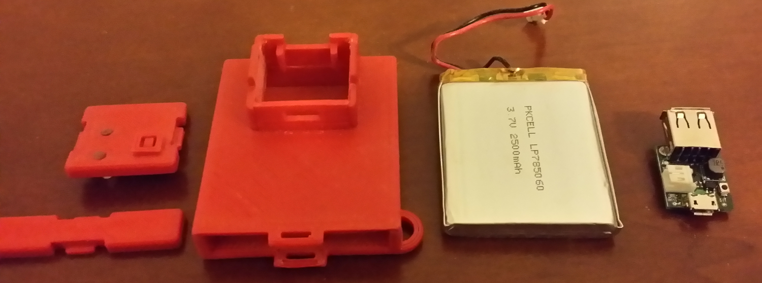
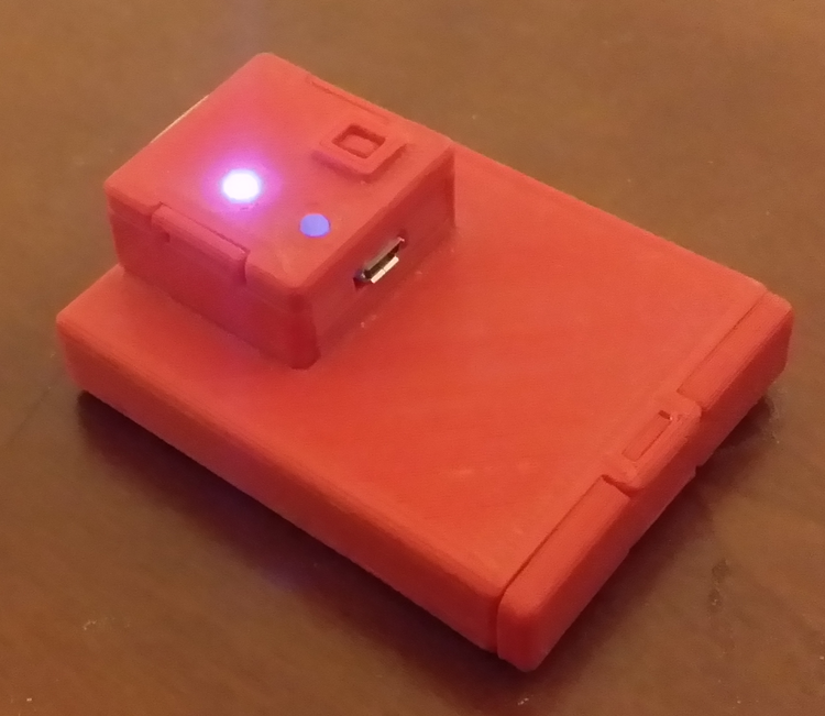
As a TA for junior design at SCU, I had to create a project for the students to design and build. A USB phone charger was chosen. After the class was over, I decided to build a new phone charger with all the "lessons learned" and some additional circuitry. The PCB components were hand soldered. I built a total of 10 of these devices and gave them away as gifts to people. The bottom of each case has the person's name 3D printed on it. There are two LEDs on the top of the device. The illuminated LED in the picture below indicates the output power is turned on. The other LED is the charging status. When the charger is recharging the battery, the charging LED will be orange. When the battery is done charging, the LED will turn green. The small square above the LEDs is the on/off button. A latching transistor is toggled by pressing the button.
Enhanced Phone Charger RepositoryEnhanced Phone Charger Pictures
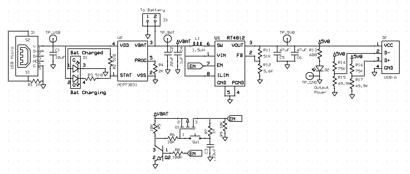
Enhanced Phone Charger Schematic
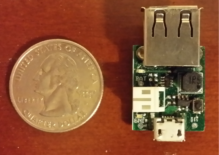
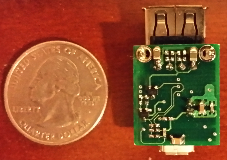
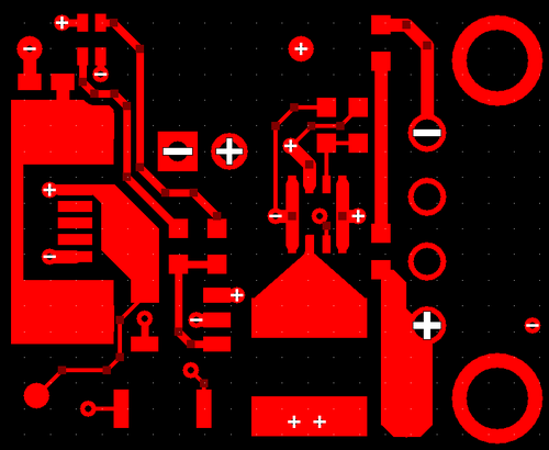
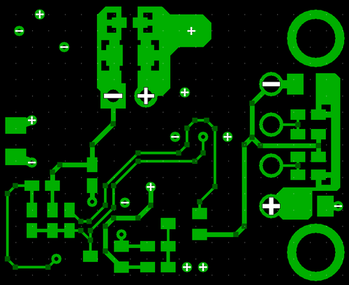
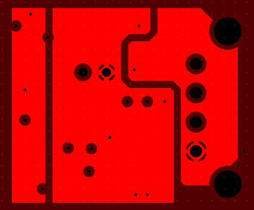
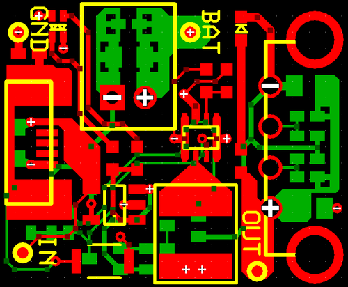
Enhanced Phone Charger PCB Design

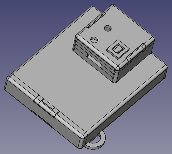
Enhanced Phone Charger CAD Enclosure