FIR Channel Filter Overview
The FIR channel filter was to be designed with the following parameters:
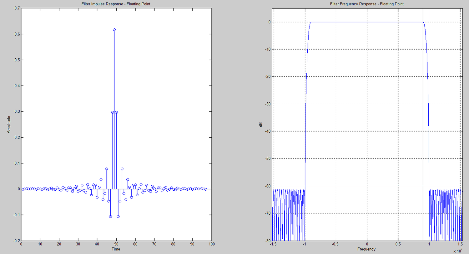
1. The length of the filter is to be N = 97
2. The pass-band frequency edge is fp = .9 X 20E6
3. Signal sample rate fs = 30.72E6
4. The highest side lobe is to be -60 dB with respect to the carrier
5. The filter is to process complex input data
Two Solutions were to be tested:
1. fclk = 307.2MHz. Include a 10% margin for the FPGA timing specification
2. fclk = 245.76MHz. Include a 10% margin for the FPGA timing specification.
Matlab Design Files
MATLAB files were given as a starting point for the design and were modified for this project's specifications.
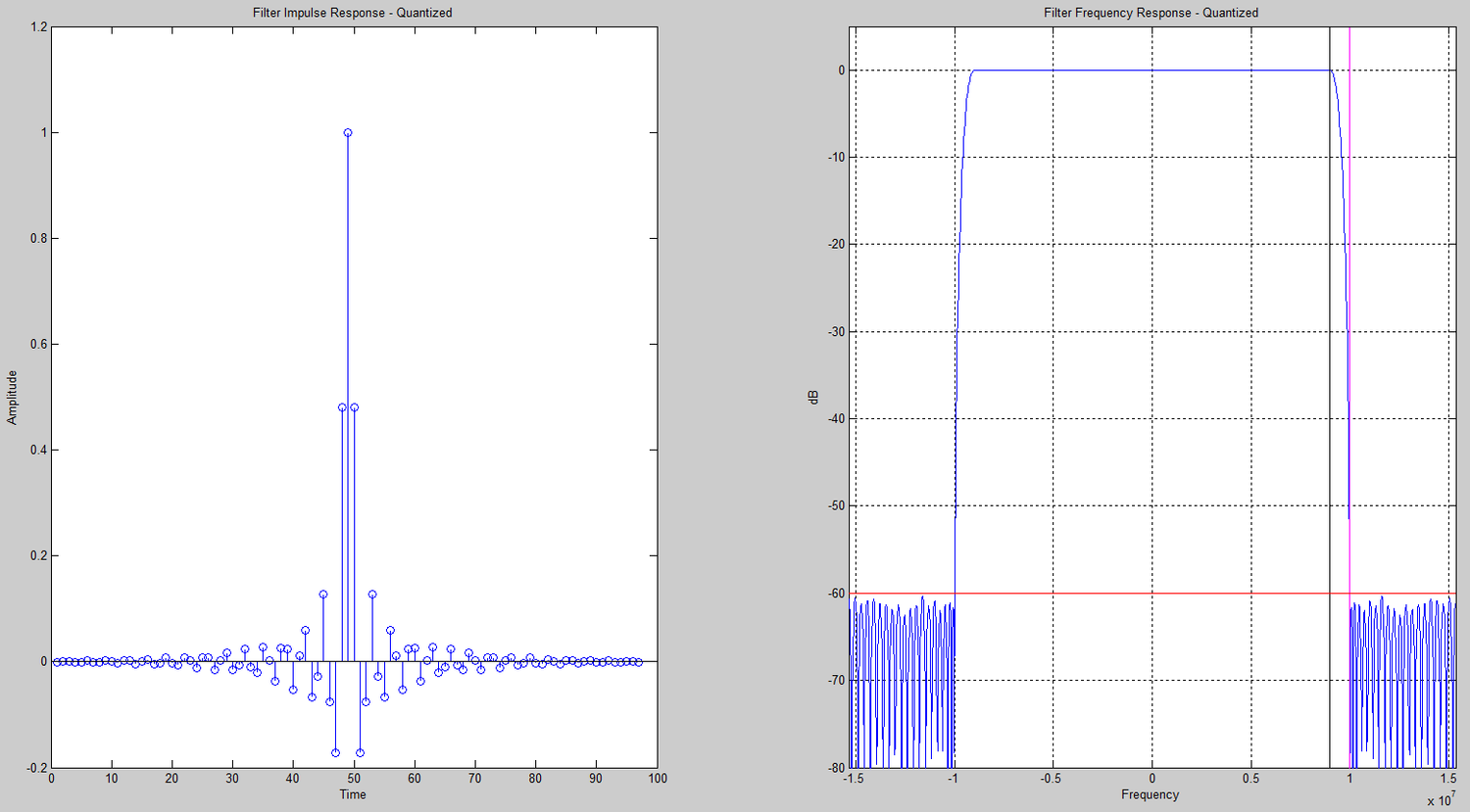
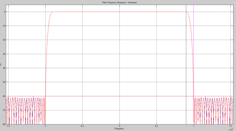
Matlab FilesMatlab Design Plots
FPGA Implementation
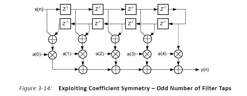
Vivado HLS Design Files
After the filter was designed in MATLAB, it was then designed in Vivado HLS. The links for the HLS source code are below:
Vivado Design FilesVivado Design Results
The following are the calculated RMS errors from the HLS test bench:
number of test vectors = 50000
Real rms error = 0.000167639
% Real rms error = 0.0167639%
Imaginary rms error = 0.000167653
% Imaginary rms error = 0.0167653%
Next are the resource utilization and timing results for the 2 solutions listed above:
Solution 1(307.2MHz with 10% margin)
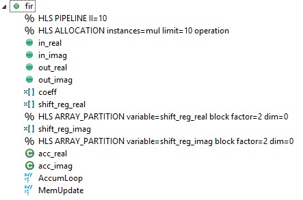

Notice the total multipliers (DSP blocks) used was 10. The total length of the filter is 97 but the middle
coefficient is 1 so only 96 multiplications are necessary. There are 2 filters, one for the real numbers
and one for the imaginary numbers. This brings the total number of multiplications up to 192. Since the
iteration interval is 10, the number of multipliers can be divided by 10: 192/10 = 19.2. The number of
multipliers is then rounded up to 20. The filters use pre-adders to take advantage of symmetry so the total
number of multipliers can be divided by 2: 20/2 = 10.
Solution 2(245.76MHz with 10% margin)
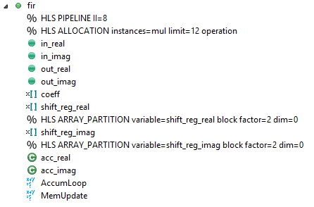

Notice the total multipliers (DSP blocks) used was 12. The total length of the filter is 97 but the middle coefficient is 1 so only 96 multiplications are necessary. There are 2 filters, one for the real numbers and one for the imaginary numbers. This brings the total number of multiplications up to 192. Since the iteration interval is 8, the number of multipliers can be divided by 8: 192/8 = 24. The filters use pre-adders to take advantage of symmetry so the total number of multipliers can be divided by 2: 24/2 = 12.
Matlab Error Calculations
Finally, the MATLAB error calculations were performed against the HLS filter output and the
golden reference data. The MATLAB RMS error calculations are below and match the HLS calculations:
RMS error, real = 0.000168
%RMS error, real = 0.016764%
RMS error, imaginary = 0.000168
%RMS error, imaginary = 0.016765%
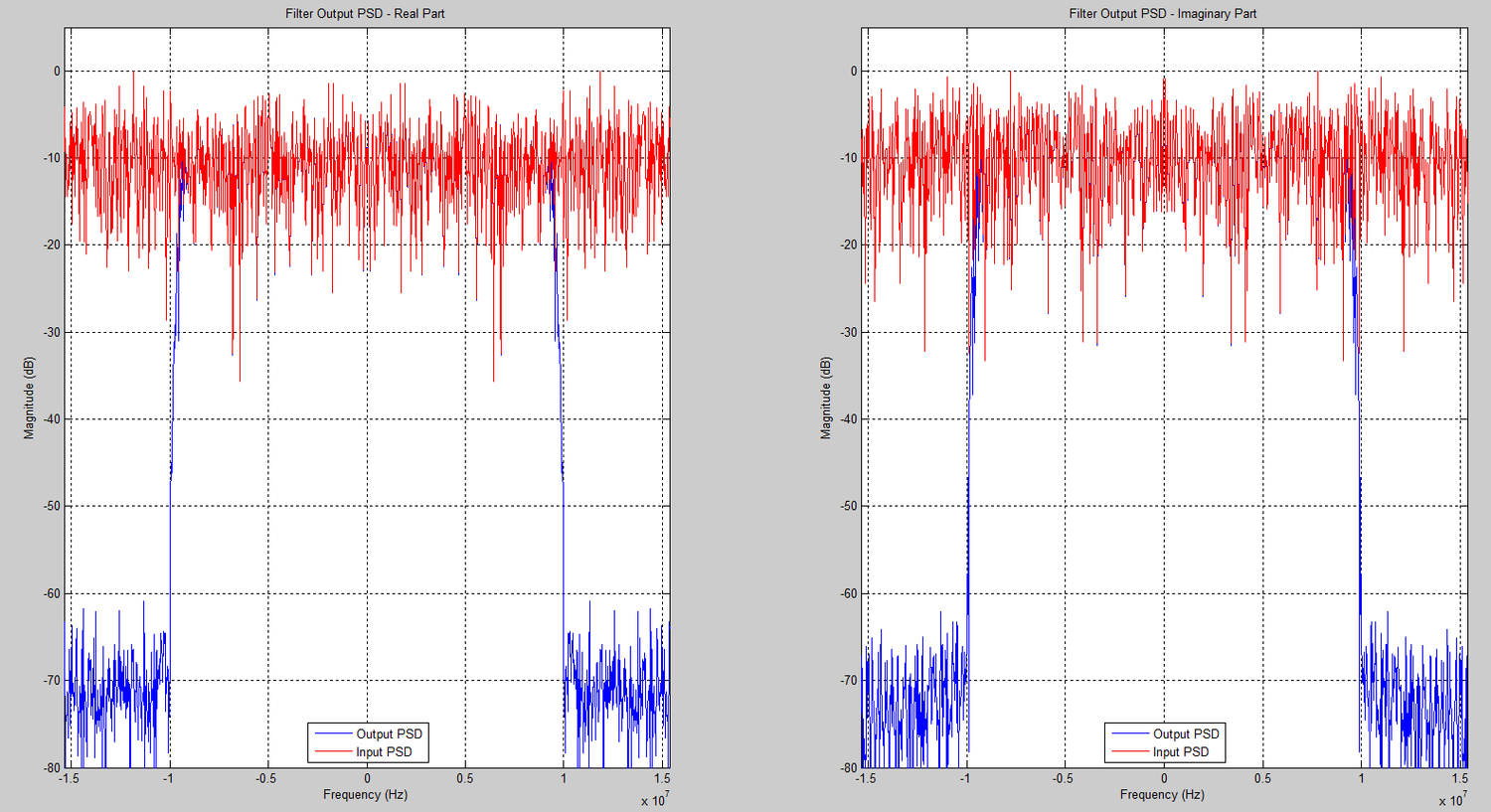
Matlab Output Plots
